Structuring data integration models and data integration architecture
Get tips on structuring data integration models and data integration architecture. Learn how to build a business case for data integration modeling and leverage process modeling.
 In this excerpt from Data Integration Blueprint and Modeling, readers will learn how to build a business case for a new data integration design process and how to improve the development process for data integration modeling. Readers will also get tips on leveraging process modeling for data integration and designing data integration architecture models, plus definitions for three data integration modeling types – physical, logical and conceptual.
Table of Contents
* Structuring data integration models and data integration architecture
* Using logical data models for data integration modeling
* Data integration tools for developing data integration models
Chapter 3
A Design Technique: Data Integration Modeling
This chapter focuses on a new design technique for the analysis and design of data integration processes. This technique uses a graphical process modeling view of data integration similar to the graphical view an entity-relationship diagram provides for data models.
The Business Case for a New Design Process
There is a hypothesis to the issue of massive duplication of data integration processes, which is as follows:
If you do not see a process, you will replicate that process.
One of the main reasons why there is massive replication of data integration processes in many organizations is the fact that there is no visual method of “seeing” what data integration processes currently exist and what is needed. This is similar to the problem that once plagued the data modeling discipline.
In the early 1980s, many organizations had massive duplication of customer and transactional data. These organizations could not see the “full picture” of their data environment and the massive duplication. Once organizations began to document and leverage entity-relationship diagrams (visual representations of a data model), they were able to see the massive duplication and the degree of reuse of existing tables increased as unnecessary duplication decreased.
The development of data integration processes is similar to those in database development. In developing a database, a blueprint, or model of the business requirements, is necessary to ensure that there is a clear understanding between parties of what is needed. In the case of data integration, the data integration designer and the data integration developer need that blueprint or project artifact to ensure that the business requirements in terms of sources, transformations, and targets that are needed to move data have been clearly communicated via a common, consistent approach. The use of a process model specifically designed for data integration will accomplish that requirement.
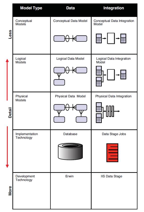
Figure 3.1 depicts the types of data models needed in a project and how they are similar to those that could be developed for data integration.
Figure 3.1 Modeling paradigm: data and data integration
The usual approach for analyzing, designing, and building ETL or data integration processes on most projects involves a data analyst documenting the requirements for source-to target mapping in Microsoft Excel spreadsheets. These spreadsheets are given to an ETL developer for the design and development of maps, graphs, and/or source code.
Documenting integration requirements from source systems and targets manually into a tool like Excel and then mapping them again into an ETL or data integration package has been proven to be time-consuming and prone to error. For example:
• Lost time – It takes a considerable amount of time to copy source metadata from source systems into an Excel spreadsheet. The same source information must then be rekeyed into an ETL tool. This source and target metadata captured in Excel is largely nonreusable unless a highly manual review and maintenance process is instituted.
• Nonvalue add analysis – Capturing source-to-target mappings with transformation requirements contains valuable navigational metadata that can be used for data lineage analysis. Capturing this information in an Excel spreadsheet does not provide a clean automated method of capturing this valuable information.
• Mapping errors – Despite our best efforts, manual data entry often results in incorrect entries, for example, incorrectly documenting an INT data type as a VARCHAR in an Excel spreadsheet will require a data integration designer time to analyze and correct.
• Lack of standardization: inconsistent levels of detail – The data analysts who perform the source-to-target mappings have a tendency to capture source/transform/target requirements at different levels of completeness depending on the skill and experience of the analyst. When there are inconsistencies in the level of detail in the requirements and design of the data integration processes, there can be misinterpretations by the development staff in the source-to-target mapping documents (usually Excel), which often results in coding errors and lost time.
• Lack of standardization: inconsistent file formats – Most environments have multiple extracts in different file formats. The focus and direction must be toward the concept of read once, write many, with consistency in extract, data quality, transformation, and load formats. The lack of a standardized set of extracts is both a lack of technique and often a result of a lack of visualization of what is in the environment.
To improve the design and development efficiencies of data integration processes, in terms of time, consistency, quality, and reusability, a graphical process modeling design technique for data integration with the same rigor that is used in developing data models is needed.
Improving the Development Process
Process modeling is a tried and proven approach that works well with Information Technology applications such as data integration. By applying a process modeling technique to data integration, both the visualization and standardization issues will be addressed. First, let’s review the types of process modeling.
Leveraging Process Modeling for Data Integration
Process modeling is a means of representing the interrelated processes of a system at any level of detail, using specific types of diagrams that show the flow of data through a series of processes. Process modeling techniques are used to represent specific processes graphically for clearer understanding, communication, and refinement between the stakeholders that design and develop system processes.
Process modeling unlike data modeling has several different types of process models based on the different types of process interactions. These different model types include process dependency diagrams, structure hierarchy charts, and data flow diagrams. Data flow diagramming, which is one of the best known of these process model types, is further refined into several different types of data flow diagrams, such as context diagrams, Level 0 and Level 1 diagrams and “leaf-level” diagrams that represent different levels and types of process and data flow.
By leveraging the concepts of different levels and types of process modeling, we have developed a processing modeling approach for data integration processes, which is as follows:
Data integration modeling is a process modeling technique that is focused on engineering data integration processes into a common data integration architecture.
Overview of Data Integration Modeling
Data integration modeling is a technique that takes into account the types of models needed based on the types of architectural requirements for data integration and the types of models needed based on the Systems Development Life Cycle (SDLC).
Modeling to the Data Integration Architecture
The types of process models or data integration models are dependent on the types of processing needed in the data integration reference architecture. By using the reference architecture as a framework, we are able to create specific process model types for the discrete data integration processes and landing zones, as demonstrated in Figure 3.2.
Figure 3.2 Designing models to the architecture
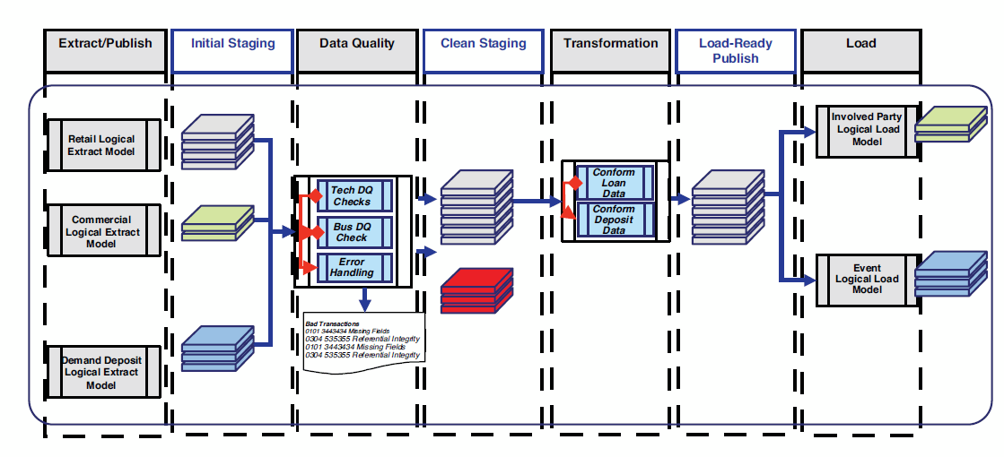
Together, these discrete data integration layers become process model types that form a complete data integration process. The objective is to develop a technique that will lead the designer to model data integration processes based on a common set of process types.
Data Integration Models within the SDLC
Data integration models follow the same level of requirement and design abstraction refinement that occurs within data models during the SDLC. Just as there are conceptual, logical, and physical data models, there are conceptual, logical, and physical data integration requirements that need to be captured at different points in the SDLC, which could be represented in a process model.
The following are brief descriptions of each of the model types. A more thorough definition along with roles, steps, and model examples is reviewed later in the chapter.
• Conceptual data integration model definition – Produces an implementation-free representation of the data integration requirements for the proposed system that will serve as a basis for determining how they are to be satisfied.
• Logical data integration model definition – Produces a detailed representation of the data integration requirements at the data set (entity/table) level, which details the transformation rules and target logical data sets (entity/tables). These models are still considered to be technology-independent. The focus at the logical level is on the capture of actual source tables and proposed target stores.
• Physical data integration model definition – Produces a detailed representation of the data integration specifications at the component level. They should be represented in terms of the component-based approach and be able to represent how the data will optimally flow through the data integration environment in the selected development technology.
Structuring Models on the Reference Architecture
Structuring data models to a Systems Development Life Cycle is a relatively easy process. There is usually only one logical model for a conceptual data model and there is only one physical data model for a logical data model. Even though entities may be decomposed or normalized within a model, there is rarely a need to break a data model into separate models.
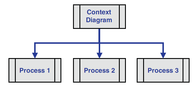
Process models have traditionally been decomposed further down into separate discrete functions. For example, in Figure 3.3, the data flow diagram’s top process is the context diagram, which is further decomposed into separate functional models.
Figure 3.3 A traditional process model: data flow diagram
Data integration models are decomposed into functional models as well, based on the data integration reference architecture and the phase of the Systems Development Life Cycle.
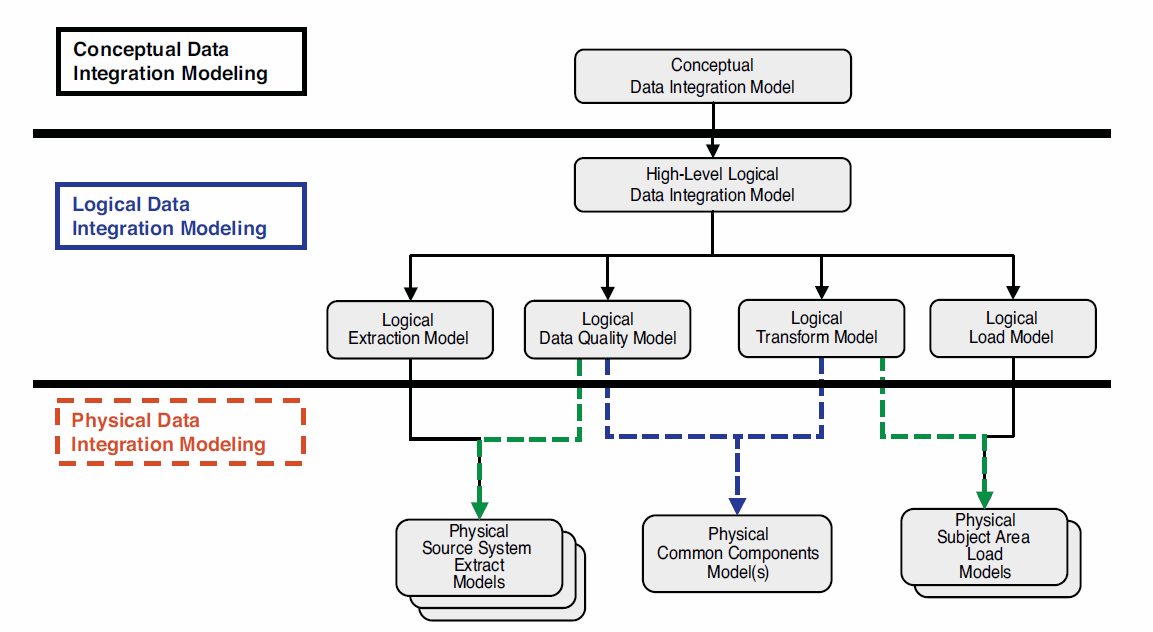
Figure 3.4 portrays how conceptual, logical, and physical data integration models are broken down.
Figure 3.4 Data integration models by the Systems Development Life Cycle
More about this book and others like it...
- Intrigued by this chapter excerpt? Download a free PDF of this chapter:
- Read more excerpts and download more sample chapters from our Data Management Bookshelf.
- To purchase the book or similar titles, visit the IBM Press website.