Using logical data models for data integration modeling
Learn about using logical data models for data integration modeling. Get an overview of using a target-based data integration design technique.
 In this excerpt from Data Integration Blueprint and Modeling, readers will learn about conceptual data integration models and logical data integration models, including high-level logical integration models. Readers will also get tips on converting logical data models to physical data integration models. In addition, they’ll find an overview of using a target-based data integration design technique and information on designing an extract verification process.
Table of Contents
* Structuring data integration models and data integration architecture
* Using logical data models for data integration modeling
* Data integration tools for developing data integration models
Conceptual Data Integration Models
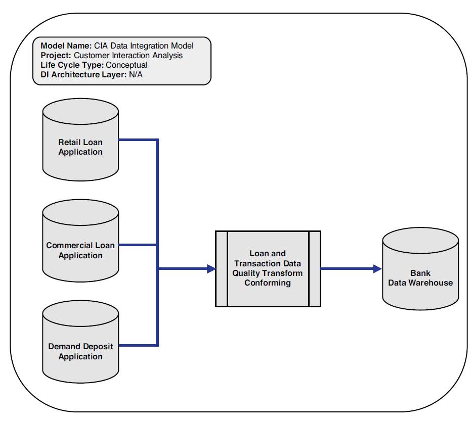
A conceptual data integration model is an implementation-free representation of the data integration requirements for the proposed system that will serve as a basis for “scoping” how they are to be satisfied and for project planning purposes in terms of source systems analysis, tasks and duration, and resources.
At this stage, it is only necessary to identify the major conceptual processes to fully understand the users’ requirements for data integration and plan the next phase.
Figure 3.5 provides an example of a conceptual data integration model.
Figure 3.5 Conceptual data integration model example
Logical Data Integration Models
A logical data integration model produces a set of detailed representations of the data integration requirements that captures the first-cut source mappings, business rules, and target data sets (table/file). These models portray the logical extract, data quality, transform, and load requirements for the intended data integration application. These models are still considered to be technology-independent. The following sections discuss the various logical data integration models.
High-Level Logical Data Integration Model
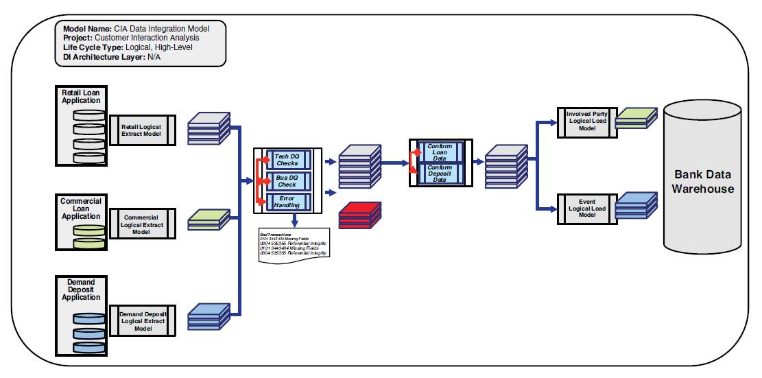
A high-level logical data integration model defines the scope and the boundaries for the project and the system, usually derived and augmented from the conceptual data integration model. A high-level data integration diagram provides the same guidelines as a context diagram does for a data flow diagram.
The high-level logical data integration model in Figure 3.6 provides the structure for what will be needed for the data integration system, as well as provides the outline for the logical models, such as extract, data quality, transform, and load components.
Figure 3.6 Logical high-level data integration model example
Logical Extraction Data Integration Models
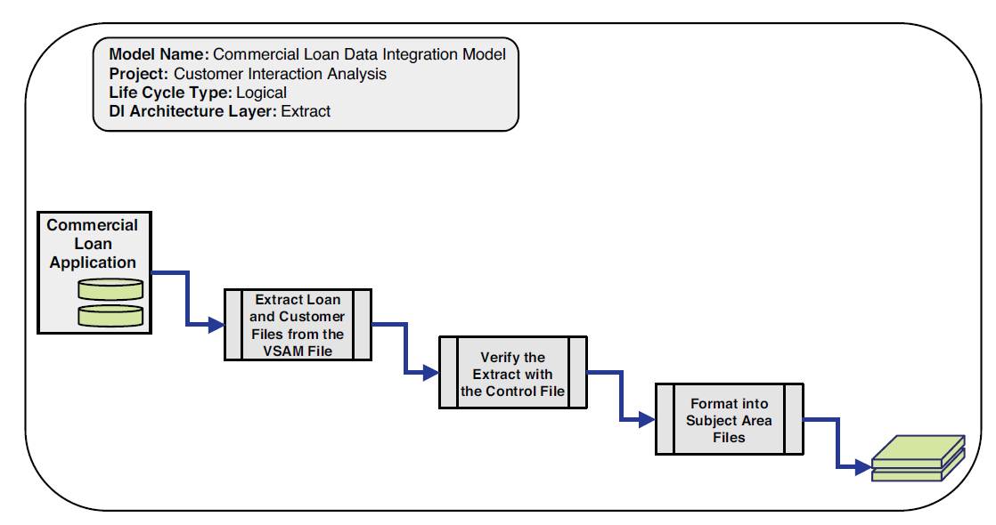
The logical extraction data integration model determines what subject areas will need to be extracted from sources, such as what applications, databases, flat files, and unstructured sources.
Source file formats should be mapped to the attribute/column/field level. Once extracted, source data files should be loaded by default to the initial staging area.
Figure 3.7 depicts a logical extraction model.
Figure 3.7 Logical extraction data integration model example
Extract data integration models consist of two discrete sub processes or components:
• Getting the data out of the source system – Whether the data is actually extracted from the source system or captured from a message queue or flat file, the network connectivity to the source must be determined, the number of tables\files must be reviewed, and the files to extract and in what order to extract them in must be determined.
• Formatting the data to a subject area file – As discussed in Chapter 2, “An Architecture for Data Integration,” subject area files provide a layer of encapsulation from the source to the final target area. The second major component of an extract data integration model is to rationalize the data from the source format to a common subject area file format, for example mapping a set of Siebel Customer Relationship Management Software tables to a customer subject area file.
Logical Data Quality Data Integration Models
The logical data quality data integration model contains the business and technical data quality checkpoints for the intended data integration process, as demonstrated in Figure 3.8.
Regardless of the technical or business data quality requirements, each data quality data integration model should contain the ability to produce a clean file, reject file, and reject report that would be instantiated in a selected data integration technology.
Also the error handling for the entire data integration process should be designed as a reusable component.
Figure 3.8 Logical data quality data integration model example
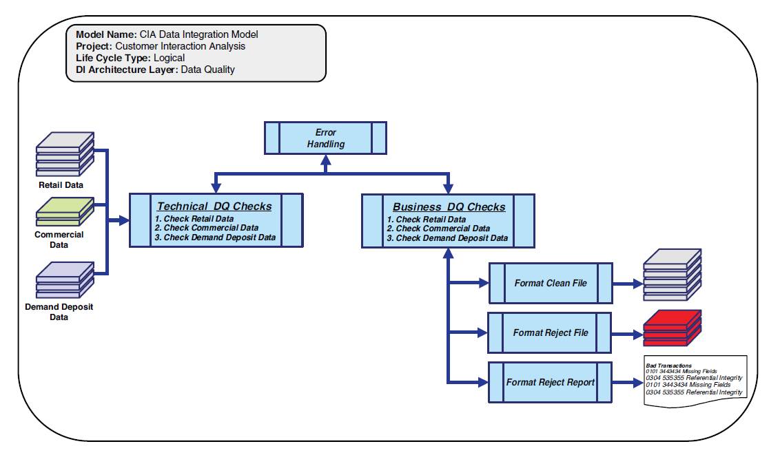
As discussed in the data quality architectural process in Chapter 2, a clear data quality process will produce a clean file, reject file, and reject report. Based on an organization’s data governance procedures, the reject file can be leveraged for manual or automatic reprocessing.
Logical Transform Data Integration Models
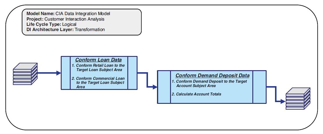
The logical transform data integration model identifies at a logical level what transformations (in terms of calculations, splits, processing, and enrichment) are needed to be performed on the extracted data to meet the business intelligence requirements in terms of aggregation, calculation, and structure, which is demonstrated in Figure 3.9.
Transform types as defined in the transformation processes are determined on the business requirements for conforming, calculating, and aggregating data into enterprise information, as discussed in the transformation architectural process in Chapter 2.
Figure 3.9 Logical transformation data integration model example
Logical Load Data Integration Models
Logical load data integration models determine at a logical level what is needed to load the transformed and cleansed data into the target data repositories by subject area, which is portrayed in Figure 3.10.
Figure 3.10 Logical load data integration model example
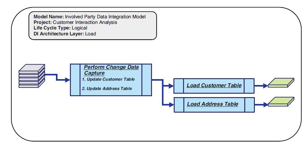
Designing load processes by target and the subject areas within the defined target databases allows sub-processes to be defined, which further encapsulates changes in the target from source data, preventing significant maintenance. An example is when changes to the physical database schema occur, only the subject area load job needs to change, with little impact to the extract and transform processes.
Physical Data Integration Models
The purpose of a physical data integration model is to produce a detailed representation of the data integration specifications at the component level within the targeted data integration technology.
A major concept in physical data integration modeling is determining how to best take the logical design and apply design techniques that will optimize performance.
Converting Logical Data Integration Models to Physical Data Integration Models
As in data modeling where there is a transition from logical to physical data models, the same transition occurs in data integration modeling. Logical data integration modeling determines what extracts, data quality, transformations, and loads. Physical data integration leverages a target-based design technique, which provides guidelines on how to design the “hows” in the physical data integration models to ensure that the various components will perform optimally in a data integration environment.
Target-Based Data Integration Design Technique Overview
The target-based data integration design technique is an approach that creates physical data integration components based on the subject area loads and the source systems that populate those subject areas. It groups logical functionality into reusable components based on the data movement patterns of local versus enterprise usage within each data integration model type.
For example, in most data integration processes, there are source system-level and enterprise-level data quality checks. The target-based technique places that functionality either close to the process that will use it (in this case, the extract process) or groups enterprise capabilities in common component models.
For example, for source system-specific data quality checks, the target-based technique simply moves that logic to the extract processes while local transformations are moved to load processes and while grouping enterprise-level data quality and transformations are grouped at the common component level. This is displayed in Figure 3.11.
Figure 3.11 Distributing logical functionality between the “whats” and “hows”
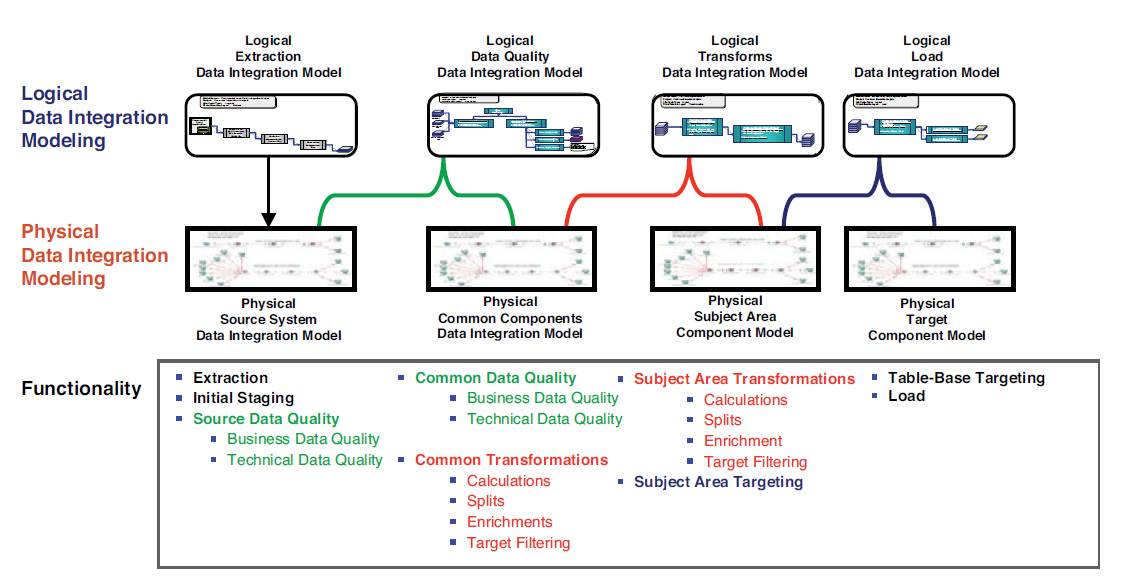
The target-based data integration design technique is not a new concept: Coupling and cohesion, modularity, objects, and components are all techniques used to group “stuff” into understandable and highly functional units of work. The target-based technique is simply a method of modularizing core functionality within the data integration models.
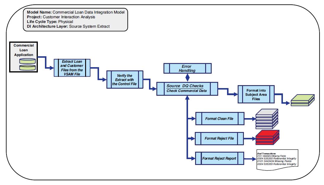
Physical Source System Data Integration Models
A source system extract data integration model extracts the data from a source system, performs source system data quality checks, and then conforms that data into the specific subject area file formats, as shown in Figure 3.12.
The major difference in a logical extract model from a physical source system data integration model is a focus on the final design considerations needed to extract data from the specified source system.
Designing an Extract Verification Process
The data from the source system files is extracted and verified with a control file. A control file is a data quality check that verifies the number of rows of data and a control total (such as loan amounts that are totaled for verification for a specific source extract as an example).
It is here where data quality rules that are source system-specific are applied. The rationale for applying source system-specific data quality rules at the particular source system rather than in one overall data quality job is to facilitate maintenance and performance. One giant data quality job becomes a maintenance nightmare. It also requires an unnecessary amount of system memory to load all data quality processes and variables that will slow the time for overall job processing.
Cross-system dependencies should be processed in this model. For example, associative relationships for connecting agreements together should be processed here.
Figure 3.12 Physical source system extract data integration model example
Physical Common Component Data Integration Models
The physical common component data integration model contains the enterprise-level business data quality rules and common transformations that will be leveraged by multiple data integration applications. This layer of the architecture is a critical focal point for reusability in the overall data integration process flow, with particular emphasis on leveraging existing transformation components. Any new components must meet the criteria for reusability.
Finally, in designing common component data integration models, the process flow is examined on where parallelism can be built in to the design based on expected data volumes and within the constraints of the current data integration technology.
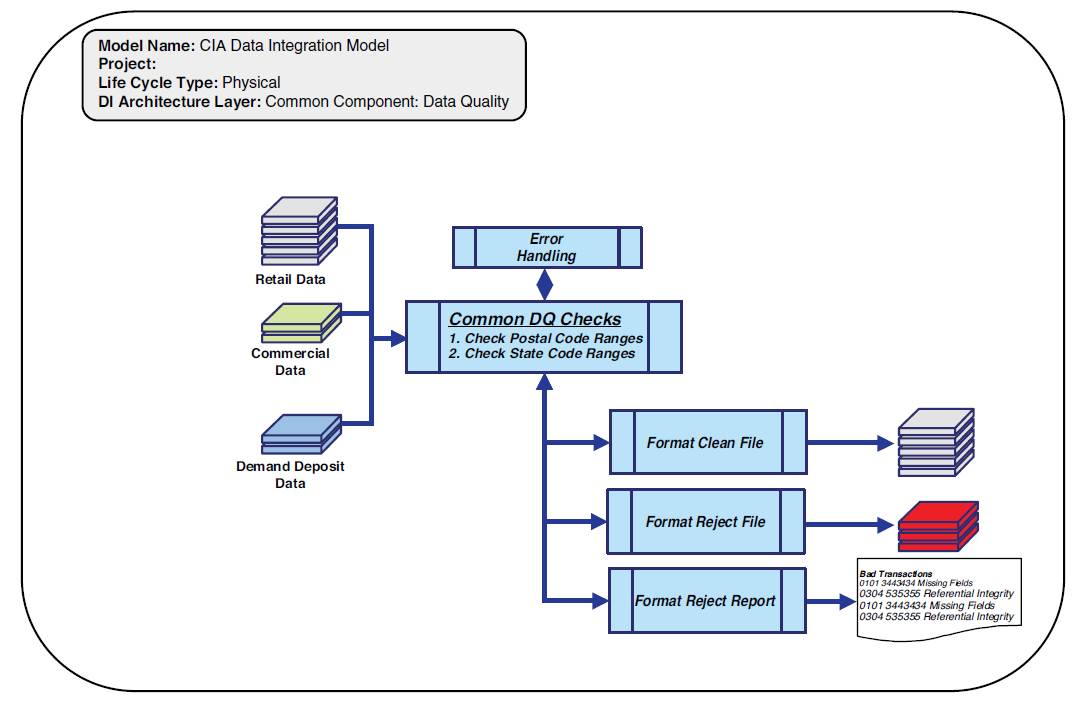
Common Component Data Quality Data Integration Models
Common component data quality data integration models are generally very “thin” (less functionality) process models, with enterprise-level data quality rules. Generally, source system-specific data quality rules are technical in nature, whereas business data quality rules tend to be applied at the enterprise level.
For example, gender or postal codes are considered business rules that can be applied as data quality rules against all data being processed. Figure 3.13 illustrates an example of a common data quality data integration model.
Note that the source-specific data quality rules have been moved to the physical source system extract data integration model and a thinner data quality process is at the common component level. Less data ensures that the data flow is not unnecessarily constrained and overall processing performance will be improved.
Figure 3.13 Common components – data quality data integration model example
More about this book and others like it...
- Intrigued by this chapter excerpt? Download a free PDF of this chapter:
- Read more excerpts and download more sample chapters from our Data Management Bookshelf.
- To purchase the book or similar titles, visit the IBM Press website.